Home List your patent My account Help Support us
Snow and Ice Removal Apparatus
[Category : - Tools]
[Viewed 2417 times]
FIELD OF THE INVENTION
The present invention relates generally to devices for removing snow. More specifically, the present invention is a wheeled apparatus for collecting snow and ice to be converted to steam. The present invention utilizes a heated water chamber within the walls of a hollow container to melt and turn snow into steam upon contacting the surface of the container.
BACKGROUND OF THE INVENTION
Snow removal can be a tedious and extremely tiring task. Typical methods of clearing snow involves physically moving the snow from one place to another using hand tools such as a shovel. This process can be very tiring and time consuming as the heavy snow must be physically moved in small increments. Therefore, it is the main objective of the present invention to provide an apparatus that requires little effort and less time in removing snow. The present invention will allow users to simply push the device through the snow for removal. Additionally, using traditional methods, the snow is simply being moved from one place to another, which has the potential to melt and form ice. Therefore, it is another objective of the present invention to provide an apparatus that is capable of completely removing the snow from the area to prevent ice from forming. The present invention will not only collect the snow, but heat it to the point of turning to steam, effectively removing it from the vicinity.
Although there are more automated devices that facilitate the removal of snow, such as snow blowers, there are still problems associated with such devices. First, these devices can be very costly, some costing thousands of dollars. Devices such as snow blowers certainly requires less effort than manual methods such as shoveling. However, the snow is still simply being moved from one place to another, having the potential to melt and form ice. Therefore, it is yet another objective of the present invention to provide an apparatus that is cheaper and more effective than current devices for removing snow from the vicinity. The present invention will collect, melt and turn the snow into steam so that the user does not have to worry about the displaced snow melting and turning to ice.
BRIEF DESCRIPTION OF THE DRAWINGS
FIG. 1 is a perspective view of the present invention;
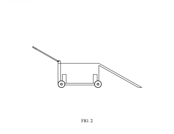
FIG. 2 is a front elevational view thereof;
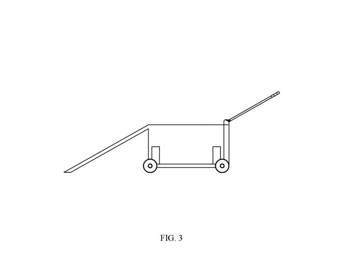
FIG. 3 is a rear elevational view thereof;
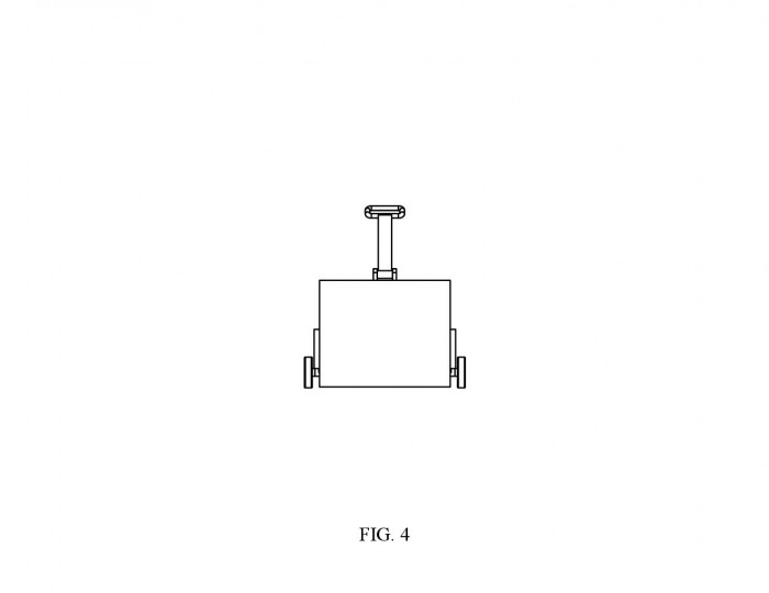
FIG. 4 is a right side elevational view thereof;
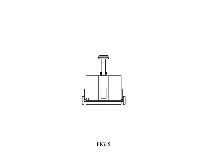
FIG. 5 is a left side elevational view thereof;
FIG. 6 is a top plan view thereof;
FIG. 7 is a bottom plan view thereof;
FIG. 8 is a front elevational section view of the present invention, showing the hollow water chamber and heating element;
FIG. 9 is a perspective of the present invention showing how the container can be raised;
FIG. 10 is a front elevational view thereof;
FIG. 11 is a rear perspective view of the present invention showing how the battery compartment and water chamber can be opened; and,
FIG. 12 is a detailed perspective view of the adjustable handle mechanism.
DETAIL DESCRIPTIONS OF THE INVENTION
All illustrations of the drawings are for the purpose of describing selected versions of the present invention and are not intended to limit the scope of the present invention.
The present invention is a device for removing snow and ice. The present invention utilizes a hollow container on wheels to collect, melt and convert snow into steam. A ramp will facilitate the collection of snow. The snow will be scooped into the container via the ramp when pushed through snow. The walls of the container, as well as the ramp, will be hollowed for water to be held. The hollowed region holding the water is known as the water compartment. The water within the water compartment will be heated via a heating element arranged within the water compartment. Heating the water will in turn heat the surfaces of the container. When the snow comes into contact with the heated surface, it will melt and turn to steam. The present invention provides a much simpler and cost effect way of removing snow.
The present invention is a snow removal device that comprises a container, ramp, battery compartment, adjustable handle and a height adjustment mechanism. The container is a hollow, rectangular component with an opening at the top surface. Snow will be collected into the container to be melted and converted to steam. The container further comprises a water compartment, a handle mount and a battery compartment. The water compartment is a hollow region within the walls of the container. All four walls and the base will be hollow for water to be held, as depicted in FIG. 8. The water compartment further comprises a water compartment door, a drain and a heating element. The water compartment door is a rectangular component arranged to the top surface of the rear wall of the container, as depicted in FIG. 6 and 11. The water compartment door will be hinged and have a locking mechanism so that the user can access the water compartment to fill it with water, as well as to secure it shut. The drain is a circular component that is arranged to the lower rear wall surface of the container, as depicted in FIG. 5 and 11. The drain is a plug like component that will allow the user to empty the water compartment when necessary. The drain will be threaded or have a twist lock mechanism to allow for a seal when closed to prevent leaking. The heating element is arranged to the base of the water compartment, as depicted by the component protruding from the base of the water compartment in FIG. 8. Once the water compartment is filled with water, the heating element will heat the water, and in turn heat the container. It is understood that more than one heating element may be necessary in order to heat the water, and in turn the container, to the desired temperature for converting snow into steam. A plurality of wires will connect the heating element to the batteries to power the device. A battery compartment is arranged to the rear surface of the container, as depicted by the rectangular protrusion in FIG. 5-7. The battery compartment further comprises a battery door. The battery door will be hinged and have a locking mechanism so that the user can replace the batteries when needed, as well as to secure it shut. FIG. 11 depicts how the battery compartment can be accessed via the battery door. Power buttons and controls may be arranged to the battery compartment to turn the device on/off as well as to control the temperature of the heating element. The handle mount is a hinge type component that will allow for the adjustable handle to be rotatably attached. The handle mount is arranged to the top surface of the rectangular component protruding from the rear of the container, also known as the battery compartment. The handle mount is essentially two solid U shaped components with a cylindrical rod horizontally placed between. The handle mount further comprises adjustment holes. The adjustment holes are circular cutouts arranged to the face of the solid U shaped components. The adjustment holes will allow for varying handle positions and will accept the adjustment pins of the adjustable handle.
The handle position and height of the present invention will be adjustable. The adjustable handle is an elongated component that further comprises a push lock mechanism with locking pins, a cylindrical mount and a handle. The cylindrical mount will be arranged concentrically around the cylindrical rod of the handle mount to allow it to be rotatably attached. The push lock mechanism will actuate the locking pins and allow the adjustable handle to be secured in various positions. The locking pins will engage with the adjustment holes of the handle mount, as depicted in FIG. 12. The height adjustment mechanism will allow for the present invention to be lowered or raised for varying depths of snow. The height adjustment mechanism is a flat rectangular platform that further comprises adjustment arms, adjustment arm inserts, axles and wheels. The adjustment arm inserts are arranged to the outer surface of the left and right walls of the container as depicted by the rectangular components protruding from the sides of the container in the figures. The adjustment arm inserts will be hollow and have an opening on the bottom surface for the adjustment arms of the lowering mechanism to be inserted. The adjustment arms are rectangular components protruding from the top surface of the height adjustment mechanism platform. The adjustment arms are able to lock into various heights within the adjustment arm inserts to allow the user to lower and raise the entire container to the desired position. The axles are cylindrical components protruding from the left and right sides of the height adjustment mechanism platform. Wheels will be concentrically arranged onto the axles to provide a rolling platform for the present invention. FIG. 9 and 10 depicts how the height adjustment mechanism can raise the container to a desired height. It is understood that there are various ways to implement the handle adjustment and height adjustment mechanisms without departing from the spirit and scope of the invention. For example, the adjustment arm inserts may be integrated into the wall of the container, without interfering with the water compartment, instead of protruding from the sides of the container walls.
The ramp will facilitate the transfer of snow into the container. The ramp is an inclined component protruding from the upper front surface of the container, as depicted in FIG. 1-3. The ramp is an extension of the container itself and is not a separately attached component. The ramp further comprises a water compartment. The container water compartment and ramp water compartment are one continuous enclosure, as depicted in FIG. 8. It may be necessary to add additional components to facilitate the collection of snow as well as to prevent damage to the ramp. For example, a rubber cap may be arranged to the end of the ramp. This way, if the device comes into contact with uneven ground, the rubber will provide some flexibility rather than getting caught and potentially causing damage to the ramp. Further, it may be necessary to add a lip or rails to the sides of the ramp. This way, when the snow is being scooped into the container, it does not fall off the sides of the ramp. Small variations such as these may be necessary to maximize the effectiveness of the snow collection method.
In another embodiment of the present invention, the height will not be adjustable. In this configuration, the wheels will be fixed to the container, without a height adjustment mechanism. Rather than being able to adjust the height of the container, the user will be able to adjust the angle of the ramp. The ramp will be rotatably attached to the container and have a locking mechanism to allow the user to position and lock the ramp at varying angles. This essentially provides the same height adjustability to collect snow of varying depths without the need for the height adjustment mechanism.
In yet another embodiment of the present invention, a motor and receiver may be integrated into the snow removal device for wireless control. In this configuration, the user will not have to manually push the device. Instead, the user will be able to remotely control the device via a remote controller. It may be necessary to add additional motorized mechanisms to allow for wireless height adjustments to scoop snow of varying depths. Under this configuration, a handle will be unnecessary and may be removed from the present invention. All adjustability aspects of the invention will be remotely controlled.
Although the invention has been explained in relation to its preferred embodiment, it is to be understood that many other possible modifications and variations can be made without departing from the spirit and scope of the invention.
 Patent publications:
No publication
Asking price:
Make an offer
Make an offer
 Great invention
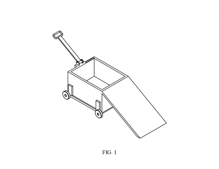
[ Home | List a patent | Manage your account | F.A.Q.|Terms of use | Contact us]
Copyright PatentAuction.com 2004-2017
Page created at 2025-12-16 12:08:27, Patent Auction Time.