Home List your patent My account Help Support us
STABILIZER MECHANISM FOR VEHICLES
[Category : - Automotive Accessories ]
[Viewed 1671 times]
When a vehicle takes a curve, there is a transfer of the weight of the inner wheel to the outside, producing the inclination of the chassis.
On the other hand, in a hydraulic press with great difference of size between the pistons, it is easy to support in the small piston the load located in the large although this one is variable.
Applying this principle, it would be easy to avoid tilting the chassis by a small compensating force.
However, the suspension is also affected by the movements of the bumps, which makes it impossible to implement the press.
The mechanism that I propose is able to maintain a constant separation between the chassis and the suspension regardless of the movement of this one.
Another more complete form of exposition is the following:
When a vehicle is traveling in a straight line, the spring-damper assembly ensures that the wheels copy the irregularities of the track to improve grip and comfort.
When accelerating, braking or passing through a curve, there is a variation in the length of the spring as a consequence of the transfer of weights, having an undesirable effect on adhesion and comfort.
To minimize this, the stabilizer bar which is used introduces a force between the chassis and the suspension to avoid adverse effects.
The problem is that they act as a suspension lock to avoid rolling, but do not discriminate bumps and transmit them from one wheel to another on the same axis unless it affects both equally, as in the case of soundtracks . This results in loss of comfort and grip when the suspension is not released freely.
On the other hand are the suspensions with the active sway bars, which through the management of an automaton and a pump, introduce the necessary force to minimize the movements, having the disadvantage of energy and economic cost.
The mechanism that I invented introduce a force between the chassis and the suspension to be able to manage the inclination and the pitching with zero or reduced consumption, but without the bumps transmitted from one wheel to another.
The device that allows a constant separation between the chassis and the suspension is based on the irreversible mechanisms of transmission of the movement, which are the cam-follower and the screw spindle-nut.
By connecting one end of one of these mechanisms to an arm of the suspension and actuating the necessary amount as a function of the displacement thereof, it can be achieved that when the suspension rises, the device cuts its length and vice versa, when the suspension descends the device is extended.
This is intended to have two surfaces, one integral to the chassis and the other to the suspension, separated the same distance regardless of the position of the suspension arm, and can introduce a force without work. Taking advantage of this feature, with a small control force, generate a larger one that acts on the device and therefore on the suspension.
In order to produce this force you can choose between different mechanisms, one of the most suitable being the hydraulic one, which will consist of two pistons of different size. A large one that will be located in said gap and will cause a pulling force or compression between the chassis and the suspension. The other smaller one will be located where it is desired and will be with the one that controls the device. The greater the difference in size between the two, the smaller the force required on the small piston to obtain the desired one on the other and therefore on the suspension.
If one chooses to use a screw spindle (Figure 1), to be irreversible must have a high ratio, so much must be multiplied the movement that makes it spin depending on the suspension.
As in this case only the property of irreversibility is interesting, unlike other applications the problem can be solved by implementing several screw spindles in series connected by nuts, so that nuts and screw spindles are alternated. The more you put, the less the multiplication of the necessary spin.
You can choose to rotate the screw spindles, nuts or both.
If you choose the cam, unlike common applications, it will not be associated with a rotating shaft but the reciprocating movement of the suspension and a rotation less than 90 °. For this reason, among other options, it can be done by combining on the same axis two disc cams sharing follower (Figure 2).
According to the above hydraulic model, in the control device acting on the small piston to replace the functions of the stabilizer bar, a mechanical variant based on a mass can be chosen, as in the attached figures 1 and 2, which is pushed by the centrifugal force to compensate for inclination in bends.
However, given the current state of the art, it can be run economically and more accurately by means of automatons equipped with sensors such as accelerometers and inclinometers.
Finally, the mechanism that moves the device, either the cam or the screw spindle, is missing depending on the movement of the suspension. Different transmission methods may be used, one of the most suitable being the use of cables or chains as the guiding chain of Figure 1, since it is a small-stroke alternative movement, although it is necessary to use one for each direction of rotation of the suspension.
FUNCTIONING:
In both embodiments the suspension bushing moves by rotating the gears of the link, causing it to rise or fall.
In figure 1 the guiding chain will move the cam and this will move the follower the same amount and in the same direction that the link has made to preserve the distance between the axis of the cam and the link. That is, what goes up the link goes up the follower and vice versa.
In figure 2 it is not shown for ease of understanding, but a mechanism such as the guiding chain will also move all the screw spindles, either all the nuts or both, together with the rotation of the bushing, so that they are joined or separated with in order to obtain the same result as in the case of the cam.
In both figures the linkage is separated from the follower or the screw spindles by the hydraulic circuit, which according to the centrifugal force pushes the regulating mass in one direction or another, will cause the desired force of traction or compression in the device.
EXPLANATORY VIDEO: Link
For a better understanding in the accompanying video, I has been used a lever to extend the corrective force instead of a hydraulic system or of gears that are more practical in the reality.
In the video the idea is appreciated by acting first when riding on a bump, where the device does not interfere with the suspension in the same way as a vehicle without stabilizer bar, which is ideal in that case.
The vehicle is then traversed along a curve without the device acting, with the inclination of the chassis being appreciated.
Finally it is activated so that it generates a force that prevents the inclination even if it passes over an irregularity.
ADVANTAGES:
1. The stabilizer bars act as suspension locks, transmitting the bumps from one wheel to another. The device presented improves adhesion and comfort in both curves and straight lines, as it does not interfere with the action of the suspension even in high frequency irregularities.
2. If you opt for a control mechanism by automaton, the consumption will be zero or reduced compared to conventional stabilizers or active suspensions, since you only have to perform a force and not a work to maintain the position of the chassis.
3. Reduction of cost and weight to eliminate the stabilizer bar and even more compared to active systems and especially those that filter high frequency irregularities.
4. Greater freedom when designing underside of vehicles by dispensing with the stabilizer bar.
5. It is a known and proven technology, based on cams or screw spindles.
6. The mechanical and friction requests will be reduced since movement of the device in the bumps is not opposed to the movement of the suspension, but tends to accompany it to compensate them.
7. Unlike the stabilizer bars, even the active ones, it is possible to reduce chassis pitch by acting on the device in the same way as to avoid rolling in the curves, but taking into account the longitudinal acceleration of the vehicle instead of the transverse one.
8. Applicable to two-wheeled vehicles to avoid pitching when accelerating and braking.
9. Easy disengagement of the stabilizer function in the desired situations, such as for example, in all terrain vehicles.
10. It can complement or even replace shock absorbers.
 Patent publications:
 ES 1189908
Asking price:
Make an offer
Make an offer
 Great invention
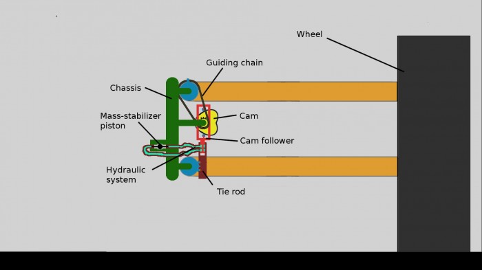

[ Home | List a patent | Manage your account | F.A.Q.|Terms of use | Contact us]
Copyright PatentAuction.com 2004-2017
Page created at 2026-01-05 10:28:17, Patent Auction Time.