Home List your patent My account Help Support us
ENERGY PRODUCING AUTOMOBILE WHEEL (EPAW) Using Centrifugal Force
[Category : - Automotive Accessories - RENEWABLE ENERGY- Pumps]
[Viewed 3392 times]
Recently I submitted a patent application (13455037) for an energy producing automobile wheel, which for abbreviated purposes I will call – EPAW.
EPAW is designed to utilize a yet untapped energy inherent in rotating automobile wheels.
More specifically EPAW is designed to capture the energy that can be realized due to the centrifugal force intrinsic in an automobile tire/wheel as it rotates.
The net result will be a decrease in fuel consumption and/or an increase in the time required between recharging batteries for hybrid and electric vehicles.
In essence, EPAW will:
• Introduce a fluid through a hollow non-rotating shaft at the center of the wheel.
• As the wheel rotates energy is gained as the fluid is accelerated radially outward due to centrifugal force, into a rotating element attached to the wheel.
• Energy is also gained by the fluid due to the angular velocity head of the fluid as it rotates.
• After gaining energy the fluid is discharged into a non-rotating disc.
• The fluid then moves from the non-rotating disc into a stationary pipe.
• The stationary pipe penetrates the non-rotating disc then the fluid produces useful energy.
• Use of an optimal mass of fluid in EPAW produces a significant net energy production after accounting for all losses.
This new found fluid energy can then be used to power a small pump/generator, producing useful energy for hybrid and electric vehicles. Thus decreasing fuel consumption and/or increase the time required between recharging batteries. Additional drawings are available upon request.
II. Detailed Description
I) Fig. 1, 1A, 1B, and 1C, are drawings to show the most basic device for ease of understanding.
a) As the tire 28 and wheel 50 rotate fluid travels from the hollow non-rotating shaft 10 into the rotating element 2.
• Energy of the fluid increases due to the centrifugal effect as the fluid moves radially outward from the shaft through the rotating element 2.
b) The fluid flows from the rotating element 2 into the non-rotating disc 12.
• The velocity head of the fluid is maximized as the fluid exits the rotating element 2.
c) The fluid moves from the non-rotating disc 12 into the stationary pipe 14.
• The fluid moves to a lower radial position as it travels through the stationary pipe. The energy gain due to the centrifugal effect is conserved however since the fluid flows through stationary components as it moves to a lower radial position.
d) The stationary pipe 14 penetrates the non-rotating disc 12.
e) To ensure the fluid does not escape from the system, fluid is contained by the inner disc sealed bearing 16, and outer disc sealed bearing 26.
• The inner/outer disc sealed bearings 16/26 are the interface between rotating and stationary parts that ultimately prevents fluid from escaping to the environment.
The fluid moves from the stationary pipe 14 to a device such as a small pump/generator to produce useful energy 60, (ref Fig 3). After energy is produced the fluid is transported back to the hollow non-rotating shaft 10.
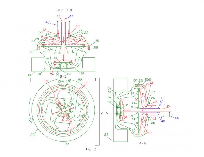
2) Fig. 2, 2A, 2B, and 2C depict a more detailed design of the EPAW fluid flow path.
a) As the tire 28 and wheel 50 rotate fluid travels from the hollow non-rotating shaft 10 into the rotating chambers 20.
• The rotating chambers 20, rotating ring header 202/204, outer rotating disc 22, and inner rotating disc 24 are one integral assembly.
• There are at least four rotating chambers 20.
• The rotating ring header 202/204, outer rotating disc 22, and inner rotating disc 24, are one integral 3600 assembly
b) As the fluid enters the rotating chambers 20 it is accelerated toward the outer diameter due to centrifugal force.
c) The fluid exits the rotating chambers 20 and enters the rotating ring header 202/204.
d) The rotating ring header 202/204 discharges fluid into the non-rotating disc 12.
• As the fluid exits the rotating ring header 202/204, the velocity head produced (due to the angular velocity of the fluid) will be an additional advantage as it flows to the stationary components.
e) The fluid moves from the non-rotating disc 12 and into the stationary pipe 14.
• The fluid moves to a lower radial position as it travels through the stationary pipe. The energy gain due to the centrifugal effect is conserved however since the fluid flows through stationary components as it moves to a lower radial position.
f) The fluid moves from the stationary pipe 14 and is used to produce a useful energy 60, (ref. Fig 3 for example).
g) After energy is produced the fluid is transported back to the hollow non-rotating shaft 10.
3) Illustrated in Fig. 2, 2A 2B, 2C, and 3, EPAW utilizes rotating and stationary components containing a fluid and therefore a means to ensure the fluid does not leak from the system is needed. As a means to minimize leakage, inner and outer labyrinth seals 30 and 32 may be used to produce a pressure drop and reduce potential leakage.
a) As the fluid is accelerated from the rotating chambers 20 and rotating ring header 202/204,
b) To the non-rotating disc 12 and,
c) Into the non-rotating pipe 14, a leakage path exists.
d) The leakage path is around the rotating ring header 202/204 to the outside of the non-rotating disc 12.
e) As a means to minimize leakage, inner and outer labyrinth seals 30 and 32 may be used to produce a pressure drop and reduce potential leakage.
f) Leakage that flows past the labyrinth seals can flow from the leak off line connection 40 to a reservoir 42 (ref. fig 3).
4) To ensure fluid does not escape from the system, EPAW employs use of sealed bearings.
a) Fluid that does leak past the inner/outer labyrinth seals 30/32 is contained by
• The inner disc sealed bearing 16,
• And outer disc sealed bearing 26.
b) The inner disc sealed bearing 16 is the sealed interface between,
• The inner rotating disc 24 and ,
• The non-rotating hollow shaft 10.
c) The outer disc sealed bearing 26 is the sealed interface between,
• The outer rotating disc 22 and,
• Non-rotating disc 12.
d) The lower part of the non-rotating disc 12 extends down and rigidly attaches to the non-rotating hollow shaft 10.
The inner disc sealed bearing 16 and outer disc sealed bearing 26 are the interface between rotating and stationary parts that ultimately prevents fluid from escaping to the environment.
• Mechanical losses should be minimized. The greater the diameter of the interface between stationary to rotating parts then the greater the sealing area and resulting mechanical losses. Therefore the outer disc sealed bearing 26 and inner disc sealed bearing 16 diameters have been minimized.
• As such, during design of EPAW the stationary pipe 14 was routed downward toward the center of the wheel to the greatest extent practical prior to the stationary pipe 14 penetrating the non-rotating disc 12. This allows the diameter of the outer disc sealed bearing to be minimized.
• The fluid moves to a lower radial position as it travels through the stationary pipe 14. However, the energy gain due to the centrifugal effect is conserved since the fluid flows through stationary components as it moves to a lower radial position.
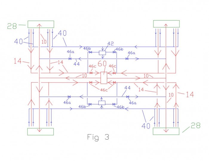
5) Fig. 3 depicts a flow diagram of EPAW in operation at higher speed as an example when used in a hybrid or electric vehicle.
a) At low velocity energy production will not be optimized. Therefore it is desirable to store the fluid in a reservoir until the vehicle has reached a pre-determined speed.
b) Once this speed is attained control valve 46b is closed, control valve 46a and 46c are open,
c) This allows fluid to flow from the reservoir 42 to the non-rotating hollow shaft 10,
d) And flow to the rotating chambers 20 etc.
e) Fluid flows from the rotating chambers to a device to produce useful energy 60.
f) As fluid flows from the reservoir 42, to the non-rotating hollow shaft 10,
g) And to the rotating chambers 20 etc.,
h) Air is displaced from the:
• rotating chambers 20,
• labyrinth seals 32 and 30,
• area between the rotating disc 22,
• and stationary discs 12 and 24.
i) The displaced air flows through the leak-off line 40 back to the reservoir 42.
j) Once the rotating shaft 10 and rotating chambers are filled and vented then flow is from a device to produce useful energy 60 back to the non-rotating hollow shaft 10 etc.
• There will be minor flow from leak-off lines 40 back to the reservoir 42 during operation.
• This minor leak-off will flow from the reservoir 42 back to the non-rotating hollow shaft 10 as power is being produced in this mode of operation.
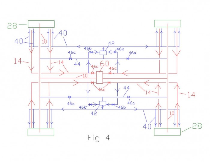
6) Fig. 4 depicts a flow diagram as the fluid is transported to the reservoir for storage at lower speeds.
a) As the vehicle slows below a pre-determined speed, for a pre-determined duration,
b) control valve 46a and 46c will close,
c) and control valve 46b will open to allow fluid to flow,
d) from the rotating chambers 20,
e) through the stationary pipe 14,
f) and back to the reservoir 42 through control valve 46b.
g) As fluid flows into the reservoir 42,
h) air from the reservoir 42 will be displaced
i) through leak-off line 40,
j) through the area between the rotating disc 22 and stationary discs 12 and 24,
k) through labyrinth seals 30 and 32 and
l) into the rotating chambers 20.
m) Air flow from the reservoir 42 is through a connection at the top of the reservoir 42 to leak-off lines 40.
n) Operation as describe above in Fig. 3 and Fig. 4 will allow:
• The energy produced by the fluid due to centrifugal force and added velocity head to be maximized at higher speed,
• while minimizing losses due to the weight of fluid and inertial effects of fluid in the rotating components at lower speed.
• Operation of control valves 46a, 46b, and 46c may be controlled with a smart computer chip. Operation of the system through opening and closing of control valves 46a, 46b, and 46c may be based on driving patterns of each individual driver. The smart chip may recognize driving patterns of each individual driver to optimize opening and closing of control valves 46a, 46b, and 46c and optimize performance of the system.
• Piping may be designed so that only one control valve 46a, one control valve 46b, one control valve 46c, and one reservoir 42 are required to accommodate all wheels.
• It may be desirable to use a vent (not shown) at the top of the reservoir to accommodate a positive or negative pressure while heating and cooling of the fluid during thermal expansion and contraction of the fluid.
• If the fluid used is water then glycol may be present so as not to freeze (or boil) the fluid. Glycol is also anti-corrosive which is desirable.
III. Ideas to Minimize Fluid Weight
1) If used in a diesel powered auto the stored diesel fuel may be used as the EPAW fluid. In a full or partially filled fuel tank there would be a sufficient mass of fuel such that a portion of the diesel fuel could be used as the EPAW fluid. Not only would the stored fuel be used to produce a useful energy due to centrifugal force/velocity head the fuel would be heated as it travels through the wheel. This is an added benefit as heated diesel fuel would increase the efficiency of the diesel engine during ignition. When the diesel fuel storage tank level has decreased to a certain level an indicator light would illuminate to indicate that if the tank is not replenished then EPAW would be disabled and the fuel would be used to propel the diesel engine.
2) Use of engine coolant should be considered as the fluid used with EPAW. As the hot coolant exits the engine it could be sent to a reservoir. The reservoir would be pressurized due to the heat gain from the engine. The fluid would then be the supply fluid to the wheel(s). This increased pressure would be an additional energy source to the fluid to produce useful energy in addition to the energy gain due to centrifugal force/velocity head. After useful energy is produced the engine coolant would flow to the radiator to be cooled. From the radiator the fluid would flow back to the engine as coolant etc. This idea would require that an additional small volume of coolant be stored in a reservoir.
3) Use of transmission fluid may also be considered as the EPAW fluid. This would also require an additional volume be stored in a reservoir. Transmission fluid could be sent to the wheel, gain centrifugal energy/velocity head, and then flow back to the transmission where the energy gained in the fluid would then be provided back to the transmission directly. This would directly decrease the power required from the external power source and increase fuel efficiency.
4) One of the ideas presented above or a combination thereof could be used as the EPAW fluid.
IV. Summary
The goal of EPAW is to provide a means to introduce a fluid into a rotating wheel and accelerate the fluid from the lowest to greatest radial diameter practical to maximize the centrifugal affect. In addition, to take advantage of the velocity head developed by the fluid as the wheel rotates. This flow can then be used as desired to produce a useful energy.
A means was needed to minimize fluid leakage from the EPAW system and so labyrinth seals 30/32 were incorporated as an option.
Sealed bearings 16/26 have been incorporated as the ultimate means for containing fluid within the system. Any fluid contained in the area of the inner/outer disc sealed bearings 16/26 flows to a reservoir 42 by the leak off line 40. Fluid from the reservoir 42 flows back to the non-rotating hollow shaft 10 when the system is in operation.
The greater the diameter of the inner/outer disc sealed bearings then the greater the sealing area and resulting mechanical losses. Therefore the inner/outer disc sealed bearing 16/26 diameters have been minimized. For the outer disc sealed bearing 26 this was accomplished during design of EPAW by routing the stationary pipe 14 back towards the center of the wheel prior to the stationary pipe penetrating the non-rotating disc 12. Since the fluid flows in a stationary (non-rotating) pipe 14 then the energy gain due to centrifugal force and velocity head is conserved even though the stationary pipe is routed to a lower diameter.
Ideas have been provided regarding types of fluid that can be used to minimize added weight and:
• take advantage of an additional untapped energy source such as pressure associated with engine coolant and,
• use of diesel fuel as the system fluid which has an added benefit of pre-heating the diesel fuel to enhance combustion efficiency.
Design of EPAW is intended to produce energy and include but not limited to applications associated with hybrid and electric vehicles. If used with a hybrid vehicle then the energy produced may be used to significantly increase the automobile manufactures published “Highway MPG”. If used with electric vehicles the invention may recharge batteries and increase the time required between recharging batteries. Use of an optimal mass of fluid in EPAW produces a significant net energy production after accounting for all losses.
Financial information
- I would like to sell my patent outright.
- This patent has not been previously sold.
 Patent publications:
 No published information
Ask the inventor for a copy of the filed application
Asking price:
Make an offer
Make an offer
 Great invention
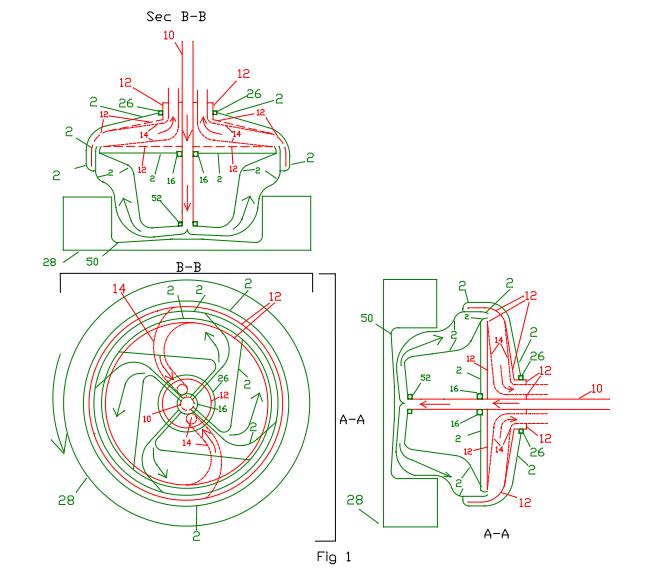
[ Home | List a patent | Manage your account | F.A.Q.|Terms of use | Contact us]
Copyright PatentAuction.com 2004-2017
Page created at 2025-10-22 1:24:04, Patent Auction Time.